Tuesday, March 7, 2017

Clap control home system


Hardware and Software Project showcasing

Project Title:   Clap control home system
     
Team name:  MBSTU_Robomaniac

Team members :

o Md. Asaduzzaman
o Md. Juwel Rana
o Md. Foyj Ullah Khan

• Institution  : Mawlana Bhashani Science and Technology University (MBSTU)
• Coach/mentor name :
    Kawsar Ahmed
    Lecturer
    Dept of ICT , MBSTU


Clap control home system:
Abstract:
 Electric switching have become more digitalized. Now people want more easier way to control their electrical equipment. In this case, our clap control system will the best option.
Physical Construction:
Instruments:
·        Arduino Uno
·        Sound sensor (digital output)
·        Relay Module          
 Process:
Connecting Sound Sensor module to Arduino is simple. The Sound sensor has 3 wire leads. One wire is for the signal, one for ground and one for 5v power. The back of the Sound  sensor module shows which wire is S (signal), - (ground), and + (5v).
The ground wire connects to the GND port on the Arduino. The + wire connects to the 5v output on the Arduino. The signal wire connects to A0 on the Arduino so that interrupts can be used. 


Why it is important:
·         In order to prevent wastage of electricity and increase the standard of living our project will be the best.
·         It will increase our utility.
·         It will save electric cost.
Condition:
·         The relay board works on 220V AC .So keep necessary safety measurements.
Error:
·         Sometimes sensor value may be scattered because of the internal frequency of Arduino microcontrollers.
Future implementation:
·         It’s our goal to make it easy to increase utility by using android app and make the project more error free.

Source code:    clap controlled home
References:
(1)
www.google.com , www.instructables.com , www.youtube.com.
(2)
Robot building for beginners –David Cook.


Simple Electrocardiogram (ECG)


                       Hardware and Software Project showcasing

Project Title:   Simple Electrocardiograph & Heart Rate Monitor (ECG)
   
Team name:  MBSTU_Robomaniac

• Team members :

o Md. Asaduzzaman
o Md. Juwel Rana
o Md. Foyj Ullah Khan

• Institution  : Mawlana Bhashani Science and Technology University (MBSTU)
• Coach/mentor name :
    Kawsar Ahmed
    Lecturer
    Dept of ICT , MBSTU


Simple Electrocardiograph & Heart Rate Monitor (ECG):

Abstract:
Heart rate is a very vital health parameter that is directly related to the soundness of the human cardiovascular system. This project describes a technique of measuring the heart rate through a PIC microcontroller. While the heart is beating, it is actually pumping blood throughout the body, and that makes the blood volume inside the finger artery to change too. This fluctuation of blood can be detected through an optical sensing mechanism placed around the fingertip by Pulse Sensor module.
Physical Construction:
Instruments:
Arduino Mega 2560
Pulse Sensor
3 LED
A desktop app to analyze Heart.
Laptop Computer (For measuring ECG graph)
Process:
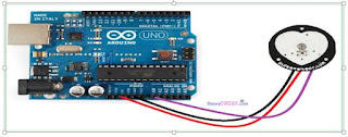
Connecting the Pulse Sensor Amped module to Arduino is simple. The pulse sensor has 3 wire leads. One wire is for the signal, one for ground and one for 5v power. The back of the pulse sensor module shows which wire is S (signal), - (ground), and + (5v).
The ground wire connects to the GND port on the Arduino. The + wire connects to the 5v output on the Arduino. The signal wire connects to A0 on the Arduino so that interrupts can be used.
Heart rate analyzing:
The Pulse Sensor Cardio Graph application illustrates heart beat information in graphical form. The application displays different heart rate variation graphs: Beats Per Minute (BPM), Inter beat Intervals (IBI), Heart Rate Frequency (Hz), Power Spectral Density (PSD), LF vs HF (Low Frequency vs High Frequency).Fast Fourier Transform is used to determine the Power Spectrum for a data set of heart beats.

Why it is important:
For heart patients, it is the most valuable medical instrument. Incase of regular checkup it can be the most cheapest device to measure his heart condition.
Reference: http://www.slideshare.net/muntasirahmed39/cardiovascular-diseasecvd


Low cost .For regular checkup it needs at least 300 /- BDT per checkup. But this device can monitor our heart every hour for thousands times with free of cost .Just need 1000/- BDT at the beginning.
It will be the best option for not only higher class people but also rural people.
Condition:
We will get better output if the heart of the patients is kept on horizontal axis (where gravity =0)
Error:
Sometimes pulse graph may be scattered because of the internal frequency of Arduino microcontrollers
In real time ECG have used 9 electrodes to measure heart rate but here is only one electrodes .
Future implementation:
It’s our goal to make it easy to measure heart rate through Android by using android app and  make the project more error free.

References:
(1) www.google.com , www.instructables.com , www.youtube.com.
(2) Robot building for beginners –David Cook.

source code and ECG app: Simple ECG